Biomechanical comparison of bone staple techniques for stabilizing tibial tuberosity fractures
Article information

Abstract
This study compared the biomechanical properties of bone-stapling techniques with those of other fixation methods used for stabilizing tibial tuberosity fractures using 3-dimensionally (3D)-printed canine bone models. Twenty-eight 3D-printed bone models made from computed tomography scan files were used. Tibial tuberosity fractures were simulated using osteotomy. All samples were divided into 4 groups. Group 1 was stabilized with a pin and tension-band wire; group 2, with a pin and an 8 mm-wide bone staple; group 3, with 2 horizontally aligned pins and an 8 mm-wide bone staple; and group 4 with a 10 mm-wide bone staple. Tensile force was applied with vertical distraction until failure occurred. The load and displacement were recorded during the tests. The groups were compared based on the load required to cause displacements of 1, 2, and 3 mm. The maximum failure loads and modes were recorded. The loads at all displacements in group 4 were greater than those in groups 1, 2, and 3. The loads at 1, 2, and 3 mm displacements were similar in groups 1 and 3. There was no significant difference between groups 1 and 3. Groups 1 and 4 provided greater maximum failure loads than groups 2 and 3. Failure occurred because of tearing of the nylon rope, tibial fracture, wire breakage, pin bending, and fracture around the bone staple insertion. In conclusion, these results demonstrate that the bone-stapling technique is an acceptable alternative to tension-band wire fixation for the stabilization of tibial tuberosity fractures in canine bone models.
Introduction
Tibial tuberosity avulsion fractures (TTAF) occur mainly in skeletally immature young dogs aged 4 to 8 months [1–3]. The tibial tuberosity originates from the quadriceps muscle through the patellar ligament [2–6]. Trauma can occur in the tibial tuberosity during muscle contraction when the knee is flexed or when the paw is firmly fixed to the floor [2–6]. The most common cause of TTAF is trauma, but other causes include running, jumping, crashing, or falling [1,4–6].
The tibia of juvenile dogs is composed of the metaphysis, proximal epiphysis, and tibial tuberosity apophysis [3–7]. The tibial tuberosity apophysis and proximal epiphysis function as ossification centers [5]. The tibial tuberosity apophysis fuses with the proximal epiphysis, while the metaphysis skeletally matures [3–7]. Pin and tension-band wire (PTBW) fixation is the preferred repair method for stabilizing TTAF [5,7,8]. Two Kirschner wires (K-wires) alone are acceptable in cases of less displacement or in young small dogs [3]. Other repair methods for TTAFs include screw fixation and tuberosity [5]. Recently, the use of external fixators has also been studied [9–11]. Possible complications of using the PTBW method in TTAF include implant failure such as pin bending, pin migration, wire breakage, proximal tibial deformity, and tibial tuberosity fractures [1,5,8].
In an in vitro mechanical study by Lai et al. [12], the PTBW fixation method, pin, and bone staples were compared biomechanically using an olecranon osteotomy model. Bone staples can be used to secure bone fragments and may be applicable to tibial tuberosity fractures [12]. Currently, no studies have been conducted on the use of bone staples to stabilize TTAF.
This study aimed to compare the biomechanical properties of bone-stapling techniques with tension-band wire fixation for stabilizing tibial tuberosity fractures using 3-dimensionally (3D)-printed canine bone models. We hypothesized that bone-stapling techniques would show a similar degree of stability to PTBW fixation.
Materials and Methods
3D-printed bone models
The bone model was produced according to the manufacturer’s instruction (Customedi, Korea). Briefly, the 3D-printed bone model was produced using computed tomography scan files of the right hind limb of an 18-month-old, 15.3-kg spayed female, skeletally mature Jindo dog. No congenital anomalies were observed. The outer cortical bone was composed of photopolymer resin, whereas the cancellous bone was composed of polyurethane foam. The patellar tendon was reconstructed using a double-structured 3 mm-wide nylon rope embedded into the tibial tuberosity.
Sample preparation
To simulate TTAFs, osteotomies were performed using a sagittal saw on all samples. The osteotomy method was adopted from the study by Verpaalen et al. [11]. Point A is the midpoint of the tibial crest. Then, from point A to point B, the metaphysis is divided into 4 to 6. Osteotomy was performed from point B to the proximal surface of the tibia in the longitudinal direction to the frontal plane. Finally, another osteotomy was performed by transversely connecting points A and B transversely [11].
Surgical application
The specimens were divided into 4 groups. Each group consisted of 7 specimens for a total of 28 specimens. Osteotomies were repaired using 4 methods (Fig. 1). Surgical application was based on a previous study by Verpaalen et al. [11]. Several common features were associated with the insertion of the K-wire (DePuy Synthes GmbH, Switzerland). The K-wire was oriented in the caudal-medial direction. The K-wire was then inserted perpendicular to the longitudinal osteotomy, including the frontal plane [11]. Finally, the K-wire was passed through the contralateral bone cortex [6]. After insertion, the K-wire was bent from the cranial side of the tibial tuberosity to the proximal side. Subsequently, the specimens were cut to approximately 3 mm in length [11].
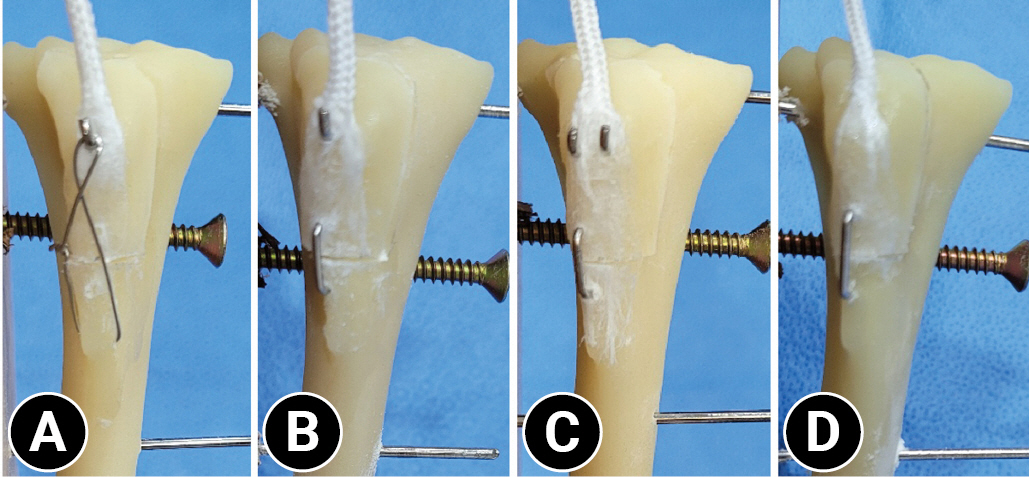
Tibial tuberosity fractures using osteotomy. (A) Group 1 stabilized with a pin and tension-band wire. (B) Group 2 stabilized with a pin and 8 mm-wide bone staple fixation. (C) Group 3 stabilized with 2 horizontally aligned pins and 8 mm-wide bone staple fixation. (D) Group 4 stabilized with a 10 mm-wide bone staple fixation.
When inserting the bone staples, a guide hole was made with a 0.8-mm K-wire using an 8 or 10 mm-wide drill bit in the caudal direction from the tibial crest with the lower transverse cutting surface of the tibial tuberosity exactly at the center. Subsequently, bone staples (1.1 mm diameter, ARIX System Bone Staple; Jeil Medical Corporation, Korea) were released with a staple holder. Force was applied to fully situate the staple bone. Finally, the installation was completed by turning the staple holder 90° (Table 1).

Fixation method for each group
Group 1 (PTBW)
The tip of a 1.4-mm K-wire was inserted from the apex of the tibial tuberosity in a normograde manner, bending the K-wire proximal to the tibial tuberosity and then cutting it, leaving 3 mm. Then, at a distance of 1.25 cm from the transverse osteotomy line, a point dividing the tibial diaphysis by 3:7 was drilled from the medial to the lateral direction of the proximal tibia using a 1.1-mm drill bit and an electric drill (Cordless Driver 3 4300; Stryker Instruments, USA) [11]. A 0.6-mm cerclage wire (DePuy Synthes GmbH) was passed through a drilled hole in the tibia and made into a figure-eight shape. The cerclage wire was tightened using the twist-knot technique, and the wire twists were bent to become tight toward the medial and caudal directions.
Group 2 (pin and 8 mm-wide bone staple)
The tip of a 1.4-mm K-wire was inserted from the apex of the tibial tuberosity in a normograde manner, bending the K-wire proximal to the tibial tuberosity and then cutting it, leaving 3 mm. Then, an 8 mm-wide bone staple was inserted.
Group 3 (2 pins and 8 mm-wide bone staple)
The tip of a 1.25-mm K-wire was inserted from the apex of the tibial tuberosity in a normograde manner, bending the K-wire proximal to the tibial tuberosity and then cutting it, leaving 3 mm. The subsequent K-wire was mounted horizontally, side by side. Then, an 8 mm-wide bone staple was inserted.
Group 4 (10 mm-wide bone staple)
Temporary fixation was performed using a 1.25-mm K-wire from the proximal area of the tibial tuberosity in the caudodistal direction while keeping the apposition of the 2 bone fragments well aligned. A 10 mm-wide bone staple was installed. The temporarily fixed K-wire was removed after installation.
Biomechanical testing
The experiments were conducted using a universal testing machine (ISO 7500; United Calibration Corporation, USA). A tensile load was applied to the nylon rope fixed to the tibia at an angle of 135°. Three 1.8-mm pins were inserted into the center of the proximal, middle, and distal bone models. Two screws were placed in front of the proximal and distal parts of the model and one screw was placed behind the middle portion to prevent the sample from rotating or leaving the plate. The lower jig held a wooden board with a stainless-steel wire rope connected to the nylon rope in the upper jig (Fig. 2). With a preload of 0.5 N applied, a tensile force of 10 mm/min was applied vertically until failure occurred.
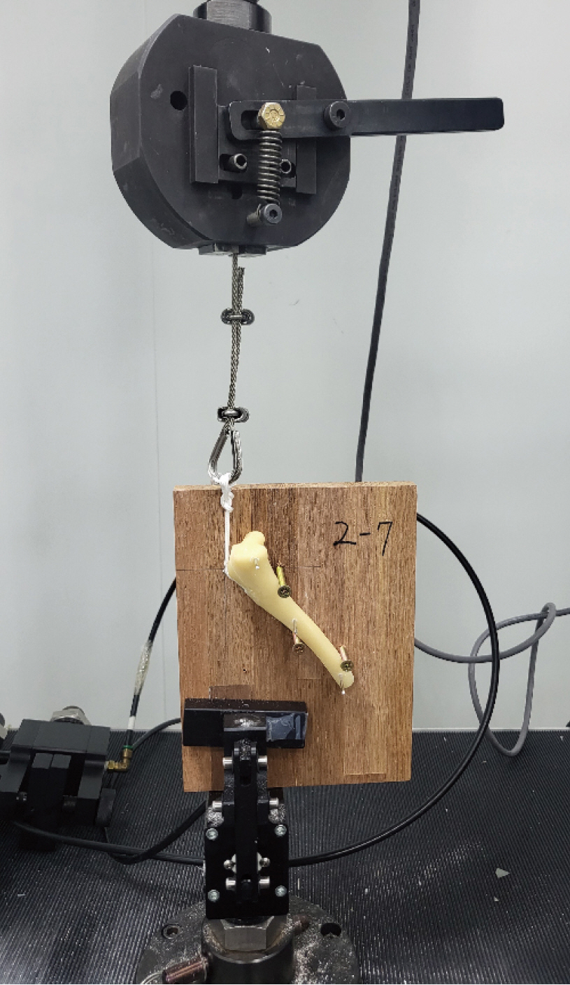
Specimen stabilized for biomechanical testing.
The groups were compared based on the load to cause displacements of 1, 2, and 3 mm. The maximum failure loads and modes were recorded. The experimental process was recorded using a camera and the scale was marked in millimeters on a wooden board prior to the review test.
Statistical analysis
Statistical analyses were performed using SPSS software (ver. 29.0; IBM Corp., USA). The Shapiro-Wilk test was used to verify the normality of the results. Groups were compared using a one-way analysis of variance (ANOVA), and Tukey’s honestly significant difference test was performed as a post hoc test. Statistical significance was set at p < 0.05.
Results
The results are summarized in Table 2. The load at 1-mm displacement was significantly higher in group 4 than in groups 1, 2, and 3. Groups 1 and 3 showed similar loads at displacements of 1, 2, and 3 mm. Group 4 exhibited a 1.42-fold greater load at 1 mm displacement than group 1 (p = 0.032). Group 4 demonstrated a 1.67-fold greater load at a 1 mm displacement compared to group 2 (p = 0.003). Group 4 had a 1.44-fold greater load at 2 mm displacement compared to group 2 (p = 0.005) and a 1.36-fold greater load at 3 mm displacement compared to group 2 (p = 0.023). Finally, group 4 exhibited a 1.32-fold greater load at 3 mm displacement compared to group 3 (p = 0.039).

Loads at 1, 2, and 3 mm displacement and maximum failure load for each group (mean ± SD)
Groups 1 and 4 provided greater maximum failure loads than groups 2 and 3. The maximum failure load in group 1 was 1.35 times greater compared in group 2 (p = 0.013), group 1 was 1.33 times greater than group 3 (p = 0.019), group 4 was 1.32 times greater than group 2 (p = 0.026), and group 4 was 1.3 times greater than group 3 (p = 0.036) (Table 2).
Tibial bone fracture or tearing of the nylon rope was commonly observed in all 4 groups. Wire breakage, bone-staple loosening, and pin bending were also observed (Table 3).

Mode of failure in each group
Discussion
This study demonstrated that bone staples can provide a fixation strength similar to that of PTBW in 3D-printed bone models. A 3D-printed bone model is different from a cadaveric bone; therefore, it does not reflect all the physical properties of bone [13]. The significance of this study is that the results were compared under the same conditions using the same materials. Therefore, this process can be easily repeated and reproduced. This may be the basis for testing cadaveric bone models.
In this study, 1.4-mm and 1.25-mm K-wires were chosen. Groups 1 and 2 were fixed with one 1.4-mm wire, and group 3 was fixed with two 1.25-mm wires horizontally aligned perpendicular to the tibial tuberosity to the osteotomy site passing through the bone cortex of the opposite site. A more stable mediocaudal direction was used compared to the caudodistal direction, which resulted in more TTAFs [6,14]. Currently, there are no guidelines for selecting the size of the K-wire based on patient weight. Thus, the K-wire thickness was chosen based on studies by Zide et al. [15] and Verpaalen et al. [11] that used 1.57 mm and 1.6 mm, respectively, in subjects weighing 20 to 30 kg [16]. Since a 15.3-kg model was used in this study, a 1.4-mm K-wire was selected as the standard size. Also, a step lower (1.25 mm) was chosen for group 3 when 2 wires were applied [16]. This study did not intend to compare the fixation strength between K-wires of different thicknesses, as in Neat et al. [17].
Osteotomy site stabilization was achieved with an 8 mm-wide bone staple in both groups 2 and 3, which each used one 1.4-mm K-wire and two 1.25-mm K-wires, respectively. A similar study on intercarpal arthrodesis performed by Toby et al. [16] showed that additional pins allowed specimens to withstand greater torsional displacement. However, the additional pins in this study did not show significant differences owing to differences in the direction of force and the location where the power was subjected. It is suspected that additional pins are more advantageous when twisting forces are applied. A figure of 8 was created using an 18-G cerclage wire in group 1. Tobias et al. [3] explains that selecting 18-G cerclage wires should be used mainly for canines weighing more than 20 kg and 20-G to 22-G for subjects weighing less than 20 kg. In this study, a 22-G cerclage wire was chosen.
Each load at displacements of 1, 2, and 3 mm was chosen as a reference point in accordance with previous studies. In human medicine, Davis et al. [18] showed that tibial tuberosity osteotomy site displacement was measured in load per millimeters. In a canine cadaveric study by Halling et al. [19], olecranon osteotomy displacements were compared at 1 mm displacement and failure was defined as a 3 mm displacement. Chalidis et al. [20] defined a displacement < 2 mm after surgery as acceptable. In addition, an ex vivo study by Lai et al. [12] performed on canine olecranon osteotomies used a 2-mm displacement load. Thus, we chose 1, 2, and 3 mm as critical points [12,18–20].
In previous studies comparing the biomechanical fixation power of the bone-stapling technique with PTBW fixation in transverse patellar fractures and olecranon osteotomy, bone staples showed increased fixation power [12,21]. In this study, groups 1 and 4 showed similar fixation power at 2 and 3 mm displacement and maximum failure load without significant differences. These studies were performed using different specimens, staple contents, and sizes, leading to different results. Schnabel et al. [21] used a human patella with a 2.5-mm diameter nitinol bone staple (12 mm × 15 mm × 12 mm), and Lai et al. [12] used a greyhound olecranon with a 2.65-mm diameter nitinol bone staple (18 mm × 18 mm × 18 mm). The staple diameter was selected based on the fragment size in each patient. In this study, a stainless-steel, 1.1-mm diameter, 10 mm × 8 mm × 10 mm bone staple was used for group 2, and a 10 mm × 10 mm × 10 mm staple was used for group 3. Thus, a smaller diameter and bone staple size are likely the causes for the lack of significant differences.
Regarding the mode of failure, tibial fractures were observed in all groups; however, in groups 2, 3, and 4 using bone staples, the locations were observed at the part where the bone staples were inserted. In group 1, fractures were identified in the middle part of the tibia, including a drilled hole for cerclage wire placement. In the staple group, the insertion site fractures were likely due to the force applied upward as the leg of the bone staple fell out first during the experiment. This resulted in a lower overall force.
Tearing of the nylon rope was also observed in all groups. However, the number of failures due to the tearing of the nylon rope was higher in group 1 than in all other groups. Zide et al. [15] compared the pin-only group, and the PTBW groups showed similar results. Unlike the pin-only group, rupture at the origin of the patellar ligament was observed in the tension-band group, suggesting that the tension-band group had a greater fixation force. In this study, the maximum failure load was the highest in the PTBW group, but the difference was not significant in the 10 mm-wide bone staple fixation group. Additional studies should be performed to define the most effective method, considering different circumstances. Verpaalen et al. [11] did not observe a mode of failure from patellar ligament rupture, which seemed to originate from the liquid nitrogen used to fix the upper zig.
Finally, this study has a few limitations. First, a 3D-printed bone model would be different from the actual bone model because of other variables, such as differences in the body’s muscles, ligaments, and physical composition. The nylon rope replacing the patellar tendon exhibited differences in appearance and reality. Therefore, additional research is needed on its application in cadavers, or to correctly apply these results in clinical practice by comparing 3D-printed models with cadavers.
In conclusion, these results demonstrate that the bone-stapling technique is an acceptable alternative to tension-band wire fixation for the stabilization of tibial tuberosity fractures in 3D-printed canine bone models.
Notes
The authors declare no conflict of interest.
Acknowledgements
The authors thank the Daegu Gyeongbuk Institute of Science and Technology for their assistance with biomechanical testing.